One year ago, my good friend from civil engineering background approached me to interpret the contour file in CAD (Computer Aided Drafting) software. The project was about building housing scheme and terrain play important role which house types should be built. When I first looked (
above) the CAD file, my first impression was I was this area is damn steep for housing area. Look how closely the contour lines are found in this area (creating steep impression). My friend told me it is gentle rising slope area but I was compelled to convert DWG into 3D model of this area.
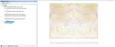 |
| The Drawing file (DWG) of CAD converted into shapefile in ArcGIS |
After receiving the drawing file (DWG), the first step was to convert it to a shapefile so that I can view in ArcGIS. For this particular project, I wasn't concerned about the metadata, the accuracy of the DWG file or the coordinate system. In ArcMap (at that time v. 9.3), I think I have used the '
Add Data' to import the file. Instantly, the file is added as multiple layers (as polylines, points and others). Since it lacks projection, ArcMap issues a warning that the DWG file lacks coordinate system. Since around 5 layers have been derived from the DWG, I decided to export all these layers to shapefiles. I right clicked on layer (i.e. NarNarGoonSurface_2012_dwg_Polyline), go to '
Export Data' and save the shapefile in my directory.
With some play with symbology, the (
above) contour map is created.
(
For more instructions, follow link: http://gpshort.uga.edu/instructions/gis/Convert%20an%20AutoCAD%20file%20to%20a%20Shapefile%20and%20Georeferencing.pdf)
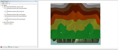 |
| Triangulated Irregular Network (TIN) in ArcMap |
First of all, in GIS (Geographic Information Science), we have different terms for representing elevation layer (i.e. DSM, DTM, DEM, TIN). The shapefiles just know we have created are in vector data format (data that stores point, lines and polygons). Triangulated Irregular Network (TIN) is vector based terrain representation. Basically, it is network of triangles connected by vertices and from there, terrain layer is generated. In the ArcToolbox on your left hand side, go to '
Data Management', the proceed to '
TIN' and from there, choose '
Create TIN'. A pop-up box appears, choose where to save the TIN file and nominate the shapefile. The (
above) TIN is generated. In ArcMap, you can start seeing that the TIN looks like in 3D format.
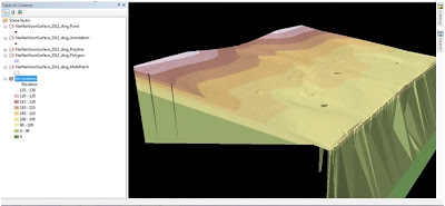 |
| 3D Terrain of the Housing Project Area |
The final stage is to bring the TIN to ArcScene (the part of ArcGIS which is focused on 3D Modelling). In Arc Scene, go to '
Add Data' and import the TIN file. Instantly, it appears as real world surface in action. In ArcScene, you can add contours, add other annotations and even do a
Fly Around.
That's wrap up the story of transforming from 2D dataset to 3D Terrain Surface.
(
For more information, refer to this link,http://crl.ap.buffalo.edu/digitalworkshop/zcorp/pdfs/Creating%203D%20Models%20Using%20ArcGIS.pdf)


No comments:
Post a Comment